Building a Quadcopter from scratch DIY : Part 1
Lets list out the things you require to build this project :
4X BLDC Motors
4X Propellers
4X Electronic Speed Controllers (ESC’s in common term)
1X 1/4 inch square aluminium tube
1X Some IMU with accelero and gyro included atleast.
1X LiPo battery as per the requirement with higher value of C
1X Microcontroller to develop a pilot board.
1X Ultrasonic ping sensor
1X pair of any kind of transmitter receiver. (Prefer higher bps)
A bunch of wires, nuts and bolts of size 3, some misc components as we will go further with this guide.
And yes, a lots of tie clips, Tape, and double tape. Never forget that.
The Basics
Here is some basic concept about quadrotor. Quardrotor as the name says has 4 rotors which helps it to fly. As there are more number of motors involved it gives higher stability plus higher scope of maneuvering. Downside of it is it eats up too much of battery so its life is never more than some 10-15 minutes. Plus the components are way costly. So get into this project only if you are ready to invest around 10K Indian rupees.
There are two types of quadrotor configuration we may opt for.
(A) (A) (B)
| x x
| x x
(B)——-|——-(B) x
| x x
| x x
(A) (B) (A)
1. Plus Configuration 2. X Configuration
You can opt for either of them, its not much of difference, I prefer plus one as it is easier to code.
A quadrotor has four motors and to do the lift off it must produce a downward thrust. All motors revolving in the same direction may produce a downward force but it will also start rotating around its own axis as it the propellers will produce its own moment. So to avoid that and introduce stability we will rotate (As from the above configuration) A motors on clockwise and B on Anticlockwise direction. What it will do is, it will cancel the moment introduced. But now hey! two motors are producing downward and others upward thrust. It wont work either right? Yes! so to avoid that, we will Put reversed propeller on A motors and on B motors with normal ones. In market the propellers are available in such pairs only so you won’t be having any problem buying them.
The motors even though are rated at same rpm, are not that alike. So they will sure produce a slight imbalance to our drone. How to balance that? We have our sensors on board which will do the trick? How, I will explain it in a moment. Lets go for the construction.
The Construction of a chassis:

Decide the size of chassis you require for your rotor. Don’t make it too long or short. A middle ground you must achieve while deciding the length. Now cut the aluminium pipe you bought into such dimensions and weld it to each other for the desired cross shape.
You will need to drill on this chassis once you will get your motors and a cardboard or an acrylic sheet to mount your circuitry on.
The Motors and ESC’s:
Motors We are gonna use are BLDC ones. Why BLDC’s? because high power compact size and affordable(kind of). How do they work? There are like three windings around their core, each of them are excited through the ESC alternatively and through lenz law the core rotates.

The motor I have used is 1200KV motor. A KV rating means at single volt what its RPM is going to be. So as for a 12V supply a 1200 KVA motor will give
= 12 X 1200 = 14400 RPM.
The thrust we will get is given at the full scale reading at 12V in the datasheet. Our motor rated 740grams of thrust with 8X4 propellers. I will tell about the propellers later. Thus the total thrust we will get is = 4 X 740 = 2960gms.
Divide it by half. and that much of weight it will easily lift.
so it is going to lift = 2960/2 = 1480gms of weight.
So anything at that range your quadrotor will easily lift.
Now ESC’s. As the name suggests ESC’s are electronic speed control circuits. There are hall sensors, some power transistors, a microcontroller to monitor it all. We are not going in much detail of how these ESC’s work. We have to give pwm to these ESC’s and what they do is they adjust the supply to the motor and sources current to it.
Our motors were rated at around 12-13 Amperes at full load so anything above that level is considered safe. So ESC’s you use should be rated a couple of Amperes over the rating of your motor.

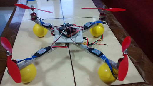
Take the marking for the holes of motor on the chassis. Keep the distance from the sensor exactly the same. Try to be accurate. Then Take the drills on the marking of size three. That is generally the size of the drills on the base motor. Now mount all the four motors on the chassis. Once done your chassis will look like this. Now mount the ESC’s also on the chassis as shown in the picture. Keep the distance same as the CG should lie exactly in the middle of the chassis. And the rotor should look symmetrical.
Propellers:
Yes without these your Quadcopter is not going to fly. As said earlier we need 2 complementary pairs of propellers for it to be able to fly. Propellers are available in different sizes. 10X3, 8X4, 3 blades, 2 blades etc. Longer the prop the speed will be more but thrust will be less and it will give more load on the motor. smaller will reduce the load. More the pitch of prop it will increase the thrust. So you need to adjust a sweet midpoint to obtain your prop by trail and error method. A 3 blade rotor is good if your motors have smaller kva rating.

Now propellers you cant just put on the shaft of your motor. You need to fix it on it right? For that there comes these coupling or caps for the propellers. Buy the appropriate size remove it into two parts. Put bottom one on the motors shaft then put propeller on it and put the other part on it and tighten the cap using the allen key.
Battery:
A regular sorts of battery won’t help in a quadrotor. A battery should be light in weight and it must allow the Motors to draw as much of 60A current without getting damaged. Thus lithium polymer batteries are our best bets. A regular lithium polymer battery will weigh around 200grams rating 11.1 with around 3AH rating. But for these batteries we must also consider the factor of C ( which is capacity according to my knowledge) under consideration. The battery I am having on my quadrotor is 3AH and 30C.
So it tells us that our rotor can take around 3 X 30 Amperes that is
=3 X 30 = 90A of current continuously without getting damaged.
As we have said earlier, Our motors are max rated at 15Amperes at full load. So in worst case condition the motors will be taking
=4 X 15 = 60A of current at max and around few mili amperes for peripherals. So we are in the safe limit.
Also 3AH rating means the battery can give 3A continuous and at that rate will last for an hour. but that isn’t a case here.
Our rotor consumes around 30Amperes while flying. So it brings our battery life to
= (3/30)*60 minutes = 6 minutes.
Yes you are right. A fully charged drone will only last for a few minutes. It isn’t the case for just my drone. The quadrotors generally won’t last above half an hour. So if you need hours of battery backup you must wait for a few years for the technology to come.
Building a Quadcopter from scratch DIY : Part 2
We tried to tell you the mechanical structure, some basic concepts and some calculations regarding building of a quadrotor.
In this article, we are going to explain the electronic side and the Algorithm to make the quadrotor work.

Assuming you are done with all the mounting parts and mechanical stuff.
This is now time to develop a control unit for your Quadcopter.
For that we are going to need a decent Microcontroller. And by decent i mean its going to need a few ADC pins, large enough memory. A handful of I/O’s, Atleast 4 PWM Outputs and also SPI/UART/I2C available on board.
Tl;dr buy an AVR or a PIC or ARM based microcontroller, these are usually available in market and very cheap, easier to implement.
I went for AVR because well, Atmel is love, Atmel is life.
Don’t power it yet as we are going to take power from our ESC’s from their onboard regulator and it is good enough for common grounding.
I am not going to give you an exact design for the board, just a basic idea and necessary stuff to build your own board.

In the above diagram I have shown how the connections from Battery to the ESC are to be made. The other 3 wires, that are Ground, 5V and Signal are to be connected to the microcontroller.
Now you have got 4 ESCs and battery connections are same for all of them. for microcontroller connections, for 5V wire connect it from just one ESC to the microcontroller. Ground wires from all, tie them together and connect them to the ground of microcontroller.
The signal pins are to be connected to the PWM channels. So while making the connections write them down somewhere as you are going to need them while you are programming your board.
Now on paper, your Drone is ready to fly. But hey, how are you going to control it. You are going to need a Transmitter+receiver to send signals to board from your remote. A remote you can make using a simple RF pair as we have covered it in the previous articles. But then these are having a really low baud rate. (Just 1200bps) so if you are good with electronics, there are many cheap solutions available for this. You can go for a low range IR remote from your TV. Or use a Xbee pair if you have got enough money. NRF chips are also great solutions for this. This all depends on your skills. I will write a tutorial for this if I get time.
So from the output of the receiver you have built, connect it to the appropriate Communication channel.
Balancing the Drone.
The thing about the drone is, even if it will look symmetrical to your eyes, it isn’t and a slight variation in weight will easily topple and crash your Quadcopter. So to avoid this we are going to make the control a closed loop system.

By closed loop i mean, we just have to take feedback from our onboard sensors and in an appropriate way adjust the speed of motor.
For this sensor you need an accelerometer, and also a gyroscopic sensor if possible.
Accelero and gyro usually are tied together in a same unit called IMU. this unit, can be either communicated to the microcontroller by serial communication or ADC port. and from these values we can balance the Quadrotor.
I will help you to imagine this scenario. Lets say a Quadcopter is not neatly balanced and the weight is a bit more on right side. So even if all motors are on the same speed, the Quadcopter will start tilting on the right side and going rightwards. We don’t want this to happen in our ideal case. To avoid this we take our feedback from accelerometer. The right side tilt is measured by our accelerometer and is given to the Microcontroller to calculate the tilt in degrees. And accordingly the speed of right side motor is increased to balance out the tilt.
I hope you understand the scenario, if not leave a comment below. I will help you if you have any difficulties.
That is basically what is all needed to build a drone. You can also add a few more sensors like Ultrasonic to measure height, or a GPS to navigate this drone. Those thing you try including in your drone once your quadrotor starts flying.
So the basic Electronic part is done. Now the only part left to do is Programming and tuning/stabilizing.

Quadcopter Programming–
Arming the BLDC’s
Assuming you have appropriate programmer and Compiler to program your board. First part you need to check if your BLDC’s are getting armed properly.
A proper arming sequence is said to be necessary just to avoid abrupt starting of Motors. The signal provided to ESC is similar to the one for servo motors. Here is a tutorial to for servo operation.
the following code will help you understand the arming signal. Just give your ESC a full PWM initially, a little delay, then No PWM signal, another delay. and finally a little signal to get your motor moving.
#define MAX_SIGNAL 179
#define MIN_SIGNAL 18
Servo motor1;
Servo motor2;
Servo motor3;
Servo motor4;
void setup() {
motor1.attach(3);
motor2.attach(5);
motor3.attach(6);
motor4.attach(10);
motor1.write(MAX_SIGNAL);
motor2.write(MAX_SIGNAL);
motor3.write(MAX_SIGNAL);
motor4.write(MAX_SIGNAL);
delay(4000);
motor1.write(MIN_SIGNAL);
motor2.write(MIN_SIGNAL);
motor3.write(MIN_SIGNAL);
motor4.write(MIN_SIGNAL);
delay(2000);
motor1.write(40);
motor2.write(40);
motor3.write(40);
motor4.write(40);
delay(3000);
}
void loop() {
motor1.write(80);
motor2.write(80);
motor3.write(80);
motor4.write(80);
delay(100);
}
increase motor1.write(80); using your remote signals and you will see, even though your quadcopter tried to fly it is very unstable.
So to reduce that, we are going to introduce Accelerometer data to the controller.
PID Tuning:

For this we are going to use a PID equation to balance this out
Here is how the above works.
kp=proportional constant;
ki=integral Constant;
kd=derivative Constant;
IDeal position= No tilt;
Current position= Some tilt;
Error= no tilt-some tilt.
add_error=add_error+Error;
Change_error=Prev_error-Error;
Adjustment=kp*Error+ki*add_error+kd*change_error;
Motor_speed=Motor_speed+Adjustment;
You can add the above code to almost everywhere, like in all of your applications.
(Adjust Kp to 0-1; ki to 0.009-0.0001; kd 0.01-0.09;)
You need to do the trial and error based calculations to implement a perfect one.
Now integrate the above pieces to all of your motors. And thats it. your Quadcopter is ready to fly. Have fun. Implement your personal ideas to it. And do tell me if you are working on something awesome.